WEEK 8: ASSEMBLY & CODE
- Mar 4, 2025
- 7 min read
Updated: Jun 12, 2025
DAY 1: DISASSEMBLY

The phone itself was fairly easy to disassemble; however, many of the core parts were hot-glued (the rotary dial and the hookswitch). The phone did not come up with a parts list, nor a reference to any instruction or diagram, and the company that sold it did not have it either. ChatGPT and common sense would have to help me guess my way through what each does!


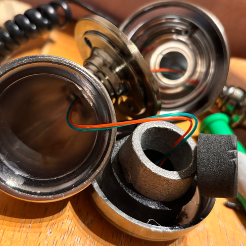
While taking a part the microphone and speaker caps on the phone, it revealed a very easy mechanism-- positive and negative wires (red & green for microphone, yellow & black for speaker), all held up by the speaker's cap so it stays set in place. Originally I wanted to install my own microphone and speaker, but I wanted to disassemble first before buying, and I'm glad I did. I decided to just use the existing wires and solder it directly into the amps (and if worse comes to worst, I can just install my own microphone and speaker).

The bottom plate held together what looks like the main brain of the rotary phone. Since I was already implementing my own computer, I knew I didn't need this, but I didn't want to take it off just in case.

I was able to disassemble the hookswitch from the phone fairly easily-- it was just held on by two screws underneath the phone, which was very accessible. After taking it out, I also discovered that it was a fairly simple mechanism! It was just a switch-- four wires connected, no labeled wires except ground. With that knowledge, I used a multimeter to test the connections: when the switch is up, ground and closed shared continuity, but when pressed, ground and open shared continuity. With that, I could isolate what wires I would need to put into the Raspberry Pi (and with ribbon wire, it would be easy to take apart).
DAY 2: ASSEMBLY (PT. 1)
AT THE DESIGN LAB:
Honestly, it seemed like luck ran out at some point because even though the phone was easy to disassemble and it seemed easy, this would become a hinderance to transfer between my own code for the Raspberry Pi, and hard to traceback any issues, making debugging incredibly difficult.
The goal was to assemble 4 core interactions:
Rotary Dial Numerical Input
Microphone (w/ Amplifier)
Speaker (w/ Amplifier)
Hookswitch
By the final presentation, I wanted to create a code that could test all of it working together, but time was being cut short, and (spoiler alert) couldn't get it to work. Let me explain why!

The speaker was easy. I was able to figure out the amplifier and what each part meant, and then soldered the phone's speaker's positive and negative wires to the amplifier, soldering wires for power directly to the Raspberry Pi, and soldering the outputs to fit into the positive and negative of the 3.5mm jack.

After taking a part the rotary dial further, I was able to figure out the mechanism of how it worked. There were LED's on the smallest chip, which was taking in power from the switch (positive & negative wires again) soldered onto the chip, and four more wires (also held on by ribbon wire) into the bigger chip. These were labeled as:
PIN 1: LED-
PIN 2: LED+
PIN 3: L2
PIN 4: L3
PIN 5: L4
PIN 6: KG
PIN 7: L1
PIN 8: HF
PIN 9: GND
With that, I was able to figure out which wire to isolate and put into the Raspberry Pi. The original plan was to take apart the ribbon wire from the big chip and lead each LED's wire into the Raspberry Pi, assign each of those GPIO pins each LED, along with GND, so that I can program it the same way the phone would.
However this would prove to not work, but I wouldn't figure that out until later.
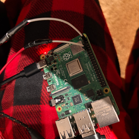
I grabbed some extra resistors along with wire from the lab (as their hours were reduced) just in case I would need it, and headed home. Look at the set up!
AT HOME:
I wanted to start testing the Raspberry Pi at the lab, but didn't have an SD adapter to edit code, so I waited until I went home. This proved to have sucked a LOT... setting up the Raspberry Pi was a mess. I don't have any images because it was a lot of terminal coding.
Long story short, for whatever reason, when setting up Raspberry Pi's with the new Imager, you have the option to "edit OS customization." I assumed this wasn't necessary as I assumed default settings should be good enough. However, it was unfortunately not the case, especially since I had to edit in "headless" mode (which essentially is editing the files remotely, since Raspberry Pi's are normally used with a monitor and keyboard attached). I had to clear and reformat the Pi so many times, adding Wifi Files, blank SSH files, only to realize the Imager can do that for me. It already specifies enabling SSH in which you have to set up the WiFi and password for it to work anyways. After setting that up, it still wouldn't work! Checking on the files, the SSH file is never set up to begin with. I then tried setting up the Debian option for Raspberry Pi on Mac OS, but it is incredibly outdated and practically impossible, so that was a waste of time.
Everything at this point became a blur as I was incredibly frustrated. However in the end, I was able to Remote SSH into it through VS Code, and signing in with the password I set up, and it worked!


I then tried testing the speaker since that was the only thing set up and ready at this point. The second it was plugged in, the speaker was already playing some white noise, so there's definitely a connection. However, the microphone was not taking in anything, so I just plugged in my headset to use the already working mic.
After learning a simple code to output speaker sounds, I was able to output a tone! It was incredibly loud, so good to know the speaker amplifier works! I asked ChatGPT to make a simple Twinkle Twinkle Little Star output using the tone code made, and it was successful!
I wanted to end the day on a good note, so I stopped there!
DAY 3: ASSEMBLY (PT. 2)

Alright, now the hard part, the microphone. After a lot of mapping out, I wanted to make these key connections from the phone's microphone to the Raspberry Pi microphone input:
Microphone (pos) -> G (gain) on the amplifier (thought to be input)
Microphone (neg) -> shared ground wire
Raspberry Pi (ground pin) -> shared ground wire
3.5mm jack (neg) -> shared ground wire
3.5mm jack (pos) -> Out on the amplifier
Raspberry Pi 3.3V -> V+ on the amplifier (thought to be power)
After a BUNCH of soldering and wire stripping and electrical taping, I got that weird contraption. Sadly after plugging everything into their respective pins, it was not working.
(Edit: Honestly looking back, I may have inputted the wrong GPIO pin (I'll explain this later) and that is why, but I can test that after.)
I thought maybe it was my lack of understanding of the amplifier (again, no instruction at all for what each hole is.) Or maybe my lack of understanding on audio inputs and how to read Raspberry Pi code, or whatever. I kew the connections were working, but for whatever reason it wasn't pulling through. I would keep plugging in my temporary mic, and that would work fine. At this point, I just cut off the amplifier entirely, and just tried to connect the positive and negative wires to the Raspberry Pi. It still did not work.
(Edit: Again, maybe this was just the wrong GPIO D:)

Moving onto the rotary dial, it also ended up not working with me. After much research and ChatGPT suggestions, I found that the LED's are used with photo resistors, which are built in, but I could not figure out how to detect it, and with lack of diagram or understanding of exactly what each pin did, I wasn't sure how to even detect each number of the dial without completely removing the original system entirely.
I was freaking out at this point, but my boyfriend gave me a really good idea: make the illusion of the dial selection determine the AI personality. Rather than the actual number, detect how many times the button is pressed, like how the hookswitch would work out.
I stripped out all of the chips, and just soldered the positive and negative wires to the Raspberry Pi. With the test code and assigning a GPIO pin as well, it.... still didn't work. I was really annoyed at this point so I moved onto the other mechanism.

The hookswitch followed the same idea. It also followed the "not working" idea too! I was so stuck and so stressed-- however, as I was looking through code, I realized that when setting up GPIO, you have to assign it "GPIO.BCM" or "GPIO.BOARD." Essentially, BOARD is what it says it is, the number is the number of the pin it is on. However, BCM is a separate labeling system-- for example: Pin 14 is not, GPIO 14, it is GPIO 17. To get it to work, you have to write the BCM label, not the BOARD label.
And with that, it worked! And so did the dial!
With all of that said and done, all (but one) mechanism works! To see the final videos, check out the presentation I made for the final presentation:
Next quarter, I want to attack the microphone issue and advancing the conversational AI. This is a little more work, but with Week 10 and Spring Break, I should be able to get back on track to set up the pedestal!


Comments